Electrification Solutions For Truck Bus Boat Construction Machine
Solutions for electrification
1. Applicable fields
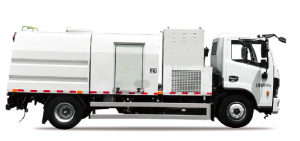
This system can be adapted to various types of vehicles, including: logistics vehicles, sanitation vehicles, buses and other commercial vehicles or special vehicles.
2. Chassis electrical topology diagram
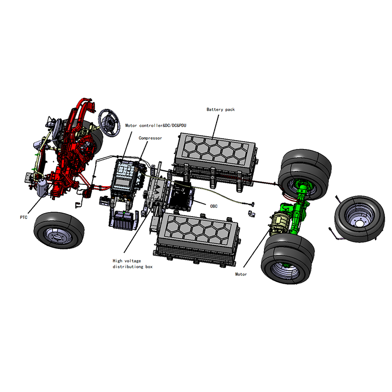
The electrical topology of the system is mainly composed of integrated motor controller, power battery, electric auxiliary system, VCU, dashboard, traditional electrical appliances, etc.
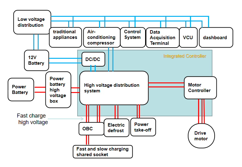
1) Low-voltage power distribution: Provide low-voltage working power to all the electrical appliances in the chassis, and at the same time realize some simple logic control;
2) Accessory system: accessory materials such as heat dissipation;
3) Control system: driver operating system, including pedals, rocker switches, shift handles, etc.;
4) Traditional electrical appliances: standard electrical appliances on fuel vehicles, including lights, radios, horns, wiper motors, etc.;
5) VCU: the core of vehicle control, controls the working status of all electric components, and detects various faults of the vehicle;
6) Data recorder: used to collect chassis operation data;
7) 24V battery: chassis low-voltage power reserve power supply;
8) Power battery: energy storage system for electric vehicles;
9) BDU: power battery high voltage power distribution control box;
10) Charging port: power battery charging port;
11) TMS: battery thermal management unit;
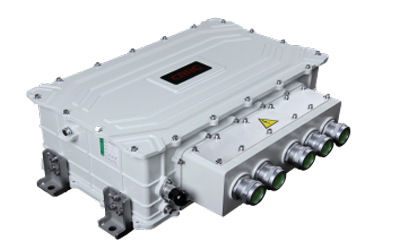
12) Integrated controller:
1) DCDC: a power module that charges the 24V battery and supplies power when the chassis is running normally;
2) High-voltage power distribution system: control the power distribution, detection and other functions of high-voltage circuits;
3) Oil pump DC/AC: Power module that provides AC power to the power steering oil pump;
4) Air pump DC/AC: The power module that provides AC power to the electric air compressor;
13) Motor controller: Debug and control the drive motor in response to the VCU command;
14) Electric defrosting: used to defrost the windshield, and has heating function at the same time;
15) Air-conditioning compressor: single-cooling electric air-conditioning, providing refrigeration for the cab;
16) Power take-off port 1/2/3: Power take-off port for bodywork operation to provide power for bodywork operation;
17) Steering oil pump assembly: electric power steering oil pump, which provides hydraulic power to the chassis steering machine;
18) Air pump assembly: electric air pump, inflates the chassis air tank, and provides high-pressure air source for the braking system;
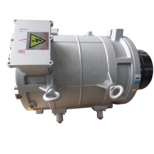
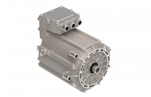
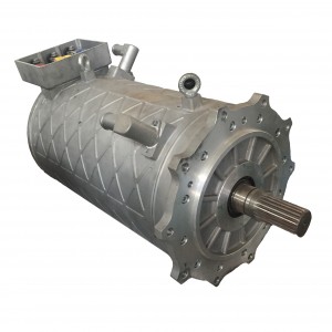
19) Drive motor: convert electrical energy into mechanical energy to drive the vehicle.
3. Working system
Working system is mainly composed of hydraulic power unit, controller, control screen, wireless remote control, Silicone panel.
1) Hydraulic power unit: power resource of upload working of special sanitation vehicles;
2) Working system control screen: according to different sanitation models, custom-develop the screen control system, with more convenient interaction, more reasonable control, and more beautiful interface;
3) Wireless remote control: remote control of all upload working operations;
4) Silicone panel: buttons to control various functions;
2) 3)4)is optional, you can take several or all of them
5)Working system controller:the core of working system, control all the upload working.

|
Item |
Picture |
|
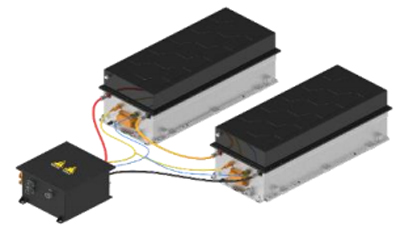
Power Battery |
 |
|
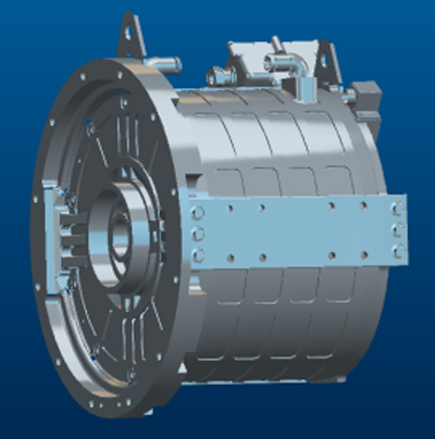
Motor |
 |
|
Integrated controller |
 |
|
Air-conditioning compressor |
 |
|
Electric cooling water pump |
 |
|
OBC |
 |
|
Drive axle |
 |
|
VCU |
 |
|
Data acquisition terminal |
 |
|
High voltage wiring harness |
 |
|
Low voltage wiring harness |
 |
|
Electric vehicle instrument |
 |


